|
 The mine clearing tanks that were based on the M4 Sherman tank chassis, are worth some extra pages. Not an experiment was too much to try to find the solution to come to a good mine clearing device. The most famous of these vehicles were the ‘Crab’ flailtanks. But other models also deserve to be mentioned on these pages. When the invasion, June 6th 1944, on the beaches of Normandy were eminent, the urge to come up with a vehicle that could sweep a clear path through a minefield became important. It had to be a relative fast vehicle that had to move under enemy fire without danger to be destroyed by the mines it was clearing. When these vehicles were produced, they would be deployed with the British 79th Armoured Division. 
It is thanks to the idea of the South-African Captain Abraham du Toit that the flail tank was developed. He thought of the idea of a rotating cylinder in front of a tank with chains with at the end a steel ball to smash landmines. The device was tested in 1941 and Du Toit went to England to develop it further. Before he left he spoke with Captain Norman Berry about the flail device. In the spring of 1942 Berry started his own working on this idea, but gave it to Major L.A. Girling to develop it further, but,… Berry never told Girling that it was idea from Du Toit. David Gustanski engineered the construction to connect it with a tank and that it could be tilted and lowered. 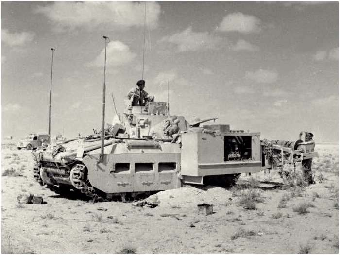
on the side the Ford 8 is visible The so called ‘rotator’ had 24 chains which was driven by a separate motor on the right of the tank. This 105 hp Ford V8 rotated the device with 100 rpm. The first devices were installed on the Matilda and Valentine tanks. It was not very successful. It was slow and the dust it created was enormous. It obscured the tank from visibility for the enemy, but smothered the crew also, they were forced to were gasmasks during operations. During the second battle for El Alamein in October 1942 there were 25 Matilda Scorpion tanks in service with the 1st Army Tank Brigade, 42nd Royal Tank Regiment and the 44th Royal Tank Regiment. But the tanks stopt moving often because of clogged up filters. 
After the ‘battle’, the Scorpion Mark II was produced. The main gun was taken out of the turret and from there the flail was handled from the position of the (former) gunner. The filters were made more efficient and other unreliable things on the device and tank were taken care of. Scorpions Mark III and Mark IV were developed and placed on the M3 Grant tank. The M3 became more and more obsolete with the introduction of the M4 Sherman tank. A handful M3 Grant Scorpions were put into action during the invasion of Allied troops on Sicily. 
Meanwhile Abraham du Toit in Engeland, unknown to him the testing of his idea in North-Africa, started on his own plan for a flail tank. At AEC Limited he designed the Matilda Baron. But there was a snag, the motor to drive the flail was placed on the side of the vehicle and was too wide for a Bailey Bridge. But, there were 60 Barons built at the factory of the Curran Brothers in Cardiff. They were only used for demonstrations and training. 
The next generation was placed on the M4 Sherman tank. These so called Pram Scorpion, was driven by the M4 his own motor. The rotor arms were bolted to the bogies and had extra support from some extra heavy rollers in front of the tracks. Experiments were also done with a model called Marquis. This had instead of a turret, an armoured housing for the engine for the rotor. None of these two types were taken into production. 
Major General Sir Percy Cleghorn Stanley Hobart and his 79th Armoured Division went for the Pram Scorpion solution to develop it further. A standard M4 got a flail that was directly driven by the engine of the M4. It would remain his gun, but lost the bow machinegun (the rotor was blocking the vision). To drive the rotor, an axel with a chain that was protruding on the right side of the tank. This was connected with a cardan shaft to a gearbox at the end of the flail-rotor. The flail, with 43 chains, rotated with the power of 285 hp. The whole contraption could move hydraulic up and down. 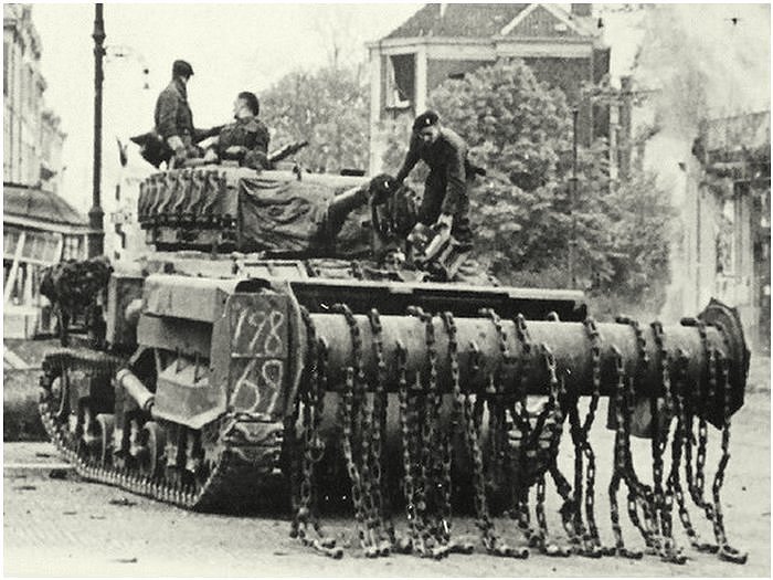
During normal driving the whole installation was lifted of the ground. When in servicemode, the whole thing was lowered, until the arms were horizontal. Disadvantage in this configuration was that in rough terrain not all of the holes could be ‘flailed’, the chains would ‘mow’ over it. To overcome this, a new arm construction was made that could follow the ground more precisely. 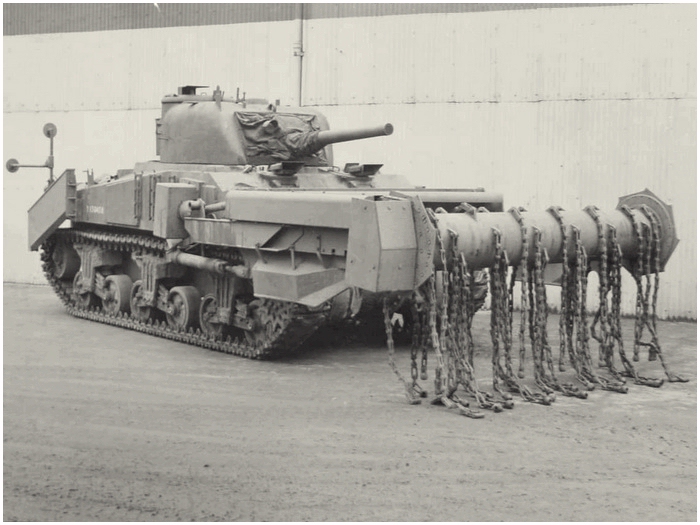
On the left flailarm an adjustable counterweight was constructed, so the height would be always the same with the terrain. Because of this, the left hydraulic adjuster was deleted. With this model, the Crab II a pathmarker was installed at the rear on both sides of the flailtank. It consisted of a container with chalk. During ‘flailing’ a speed of 2 km/ph was driven. 
Testing with the Crab was with great satisfaction, and Hobart placed them in the 79th Armoured Division for the landing in Normandy. With the 30th Tank Brigade they served until the end of the war. 
Testing was done with the Lobster. This was equipped with an open rotor for a better view at the front. The chains were connected with a horizontal extension to create more effect. But it never came to a production because of the success of the Crab II. 

One of the First anti-mine roller systems, the, de A.M.R.A. (Anti Mine Roller Attachment), was developed by the John Fowler factory in Leeds. But as it shows in the picture abovem from August 1942, the anti-mine wheels were of a light construction. They were easily damaged and even useless after a mine detonated. 
The next device with rollers was much heavier, this attachment, the Anti-Mine Reconnaissance Castor Roller (AMRCR), consisted of four heavy rollers in front of a Sherman V. Each wheel was built up from 18 steel plates. Fourteen of those were 49.5cm wide and 25.5mm thick. The other four were 66cm across and 12.7mm thick. 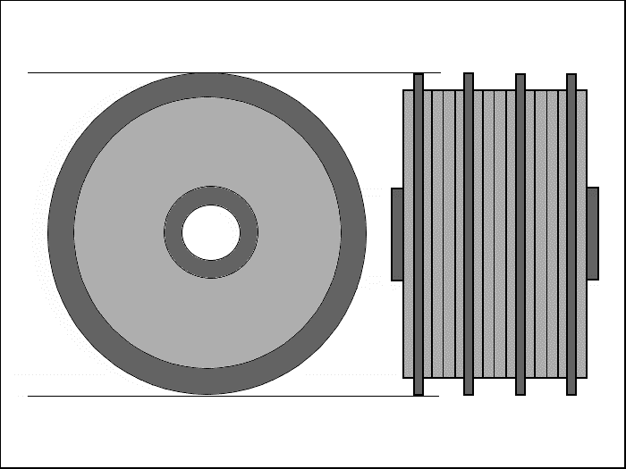
The wheels were placed in a frame. Each wheel had an individual suspension so a maximum effect was created in the field. It was possible to dislodge the whole frame from the tank by triggering small charges, so the crew could stay in the tank and be (relative) safe. It was difficult to maneuver with construction and it was not further developed. 
An installation that looked like the above Construction, with only two rollers instead of four, was the Canadian Indestructible Roller Device (CIRD). There were two versions, the (measured across the roller) 15-½ inch CIRD/Sherman (39.4cm) and the 18 inch CIRD/Sherman (45.7cm). The rollers were made out of massif steel and connected through an axel with suspension on to a frame. When a mine exploded, the complete roller shot upwards and swept forward. The frame was then lifted and the Sherman moved onwards and the roller fell back in place to ‘look’ for a next mine. The 15-½ inch CIRD had wheels with a cross section of 63.5cm and a weight of 487 kilo. The 18 inch CIRD measured 71cm and a weight of 762 kilo. During operation, the speed was around the 10 km/ph. Testing was also done with Flying Bangalore torpedo’s that were fired from the side arms. These were use to destroy barbwire obstacles and the occasional mine that came on it’s path. 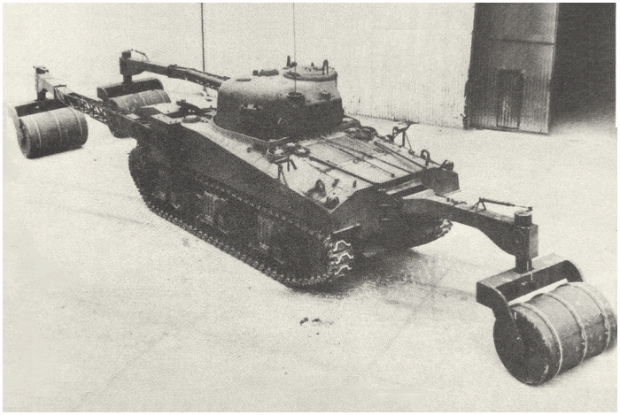
A very beautiful solution with ‘rollers’ was the mine detector Lulu. Electrical coils were placed inside three lightweight wooden barrels. Two were placed on the front and one on the rear of the tank. Were the heavy rollers used with their weight to explode the mines, the Lulu detected the mine. When one was located, a light lit and a sound signal was given inside the tank. A mine demolition team was brought forward to remove the mine. 
It looked very impressive. When in transit, the coils were neatly stacked on the reardeck of the Sherman tank. But it was a fragile construction and slow to operate. When a mine was located, the Sherman had to back up, so the demolition team could move in. More than an experimental setup was not built.
CLICK on the M32 Recovery Vehicle with the T1E1
|
